Battery Reading 12.36 Volts but Battery Still Acts Like a Dead Battery
Charging Arrangement Testspast Richard Atwell | |
Contents:
| Quite often when your battery stops charging you lot are left wondering why subsequent attempts at component replacement fail to cure the problem. I've provided a prepare of detailed steps to follow to aid you determine which parts have failed. Steps are many merely thorough to help to hunt downwards your electrical gremlins. This article just covers bus alternators and not the early style generators. |
Earlier nosotros start, there are two conventions to observe. First, VW wiring systems are negative footing which means that the negative post of the battery is connected to the vehicle body. This may seem natural but positive ground systems exists (like vintage British made Jaguars) which can exist disruptive to people who accept worked on the opposite system.
2nd, when talking almost current, in the automotive field we more than often mean conventional electric current which states that current flows from positive to negative. In reality, electrons (which are the accuse carriers) menstruum from negative to positive but the conventional system is illustrated in more texts (a concord over from the early on days of science).
Overview:

The charging organisation is made upward of 3 components: (A) the battery, (C) alternator and (C') voltage regulator. The battery is the middle of the system that produces voltage and provides storage for electric current. When the engine is off, the bombardment powers the lights and accessories. When you are trying to offset the engine, the battery powers the starter and ignition system. It also energizes the alternator which begins to produce its ain current when the alternator nears the engine'south idle speed.
The alternator charges the battery while the engine is running; without it, the bombardment would run downwardly very quickly. Although the alternator is a source of current, you might think that once yous starting time the engine you could disconnect the bombardment simply the system is not designed to operate that fashion. You should non run the engine without the battery continued especially if you take FI or sensitive electronics that always await 12-14V. The battery is integral to the proper functioning of the electrical system.
When the engine is running, the bombardment and alternator provide power simultaneously. The alternator tries to power the electrical system and accuse the battery at the aforementioned time but because the alternator's output is somewhat dependent on the engine rpm, when loads are high the battery can instantly supply more electric current when necessary. It'due south the electrical "shock absorber" in the organization which is essential a huge capacitor (measured in F not uF!). When the alternator is spinning at loftier rpm it is easily producing enough electricity to run across all of the electric current requirements.
How and when to accuse the battery is determined past the voltage regulator which controls the current flow from the alternator to the battery. It'south mounted on the firewall which acts as a ground and heat sink. The VR reads the battery voltage and varies the alternator'south output accordingly.
Because the battery, alternator and VR are so closely coupled, figuring out which i is at fault can be difficult without following the proper diagnostic steps. The diagram on the correct shows the tight electrical coupling betwixt components. Generally battery tests are elementary but determining whether the alternator or VR is at mistake can be complicated unless you understand how they work.
In the wiring schematic you can see how the alternator is indirectly connected to the bombardment via the starter solenoid. You tin can besides encounter how the ignition switch is battery powered and activates the alert lamp which serves a dual purpose: it completes a circuit that also energizes the alternator via the voltage regulator fifty-fifty before the engine has been started. What's important to note from the kickoff is that in that location are a lot of electric contacts involved. Print out this diagram and keep information technology in your glove compartment.
Because the battery is the easiest to test and the most essential, we'll effigy out how to test it outset. Then nosotros'll proceed to the voltage regulator and the alternator last. Along the style I'll explicate how each works so the reason for each tests can be understood.
Battery Tests:
Disclaimer: Electricity and bombardment acid can both be very dangerous. Electrical shorts can starting time fires. When handling batteries, use all precautions because the contents are a highly corrosive potentially explosive poison. Use ventilation, remove jewelry, wearable protective clothing and eyewear, etc.
The stock size battery for the bus is a Group 42 or Group 41 as rated by the Battery Council International (BCI). These are European mode batteries: they look the same only the terminals are reversed compared to an "American" battery. For Europe, positive is on the correct and negative on the left with the terminals facing towards you. If you purchase another grouping battery for your motorcoach, the cables might not reach if you flip it around so the terminals face the body, particularly on a 73-79 double-decker. Note that the 68-72 models have the battery cables reversed (footing strap is behind the taillight) so you could apply a United states of america bombardment.
As you tin can see, of the two batteries the dimensions are very like with the Group 41 being near 2" longer.
| Group | CCA | CA | Ah | RC | Size (inches) |
|---|---|---|---|---|---|
| 42 | 450 | 565 | 54 | 76 min | 9-v/viii x 7 x half dozen-3/4 |
| 41 | 650 | 815 | 63 | 110 min | eleven-one/2 10 6-seven/8 ten 6-five/8 |
So what do the ratings hateful?
-
Cold Cranking Amps (CCA) - How many amps that can exist delivered for xxx sec at 0F (-17C) earlier the voltage drops beneath seven.2V. That is the minimum voltage required to appoint most starters and solenoids.
-
Cranking Amps (CA) - How many amps that can be delivered in the aforementioned scenario but for 30s at 32F (zero C).
-
Amp Hours (Ah) - How much current a fully charged battery can supply for xx hours before the voltage drops below 10.5V at 80F (27C). For case, 3A delivered for 20 hours would justify an 60Ah rating. While driving, a 3A load is below the typical electric current draw which is why batteries run downward so easily.
-
Reserve Chapters (RC) - This is the fourth dimension in minutes that the jitney can be driven with the headlights on after the alternator fails. This test assumes a 25A load at 80F (27C) and is the length of time information technology takes for the voltage to drop to 10.5V. As you lot can run into the group 42 is going to final about an hour if your alternator fails at dark where as the slightly large group 41 will final fifty% longer.
The rule of thumb with regard to battery selection is to favor CCA in common cold climates and RC in warmer climates when comparing shopping. E'er use the minimum BCI group ratings in your choice procedure earlier you elect to choose another battery group that fits the battery clamp and so you don't end up picking an underpowered bombardment.
Here's a list of typical drain levels for a fuel injected engine to give you an idea of the current demands:
| Condition | Amperage |
|---|---|
| Ignition on | 3.5A |
| + parking lights | 3.8A |
| + low beams (55W) | fifteen.5A |
| + high beams (60W) | 17.2A |
| Engine on | 5.0A |
| + low beams (55W) | 17.2A |
| + high beams (60W) | 18.8A |
| + alternator | -v.0A |
As you can run into the corporeality of running time y'all'll have at night volition be slightly longer than the RC rating of you bombardment because the load is less than 25A specified by the standard. If you are running your stereo equally well, YMMV. The last entry in the table is the about interesting equally it shows the alternator powering all of the electric loads (minus the lights) while charging the battery at the aforementioned time.
Beyond size, there are two bones types of batteries that are constructed differently: starter and deep cycle. A deep cycle battery can be discharged almost completely and recharged over and over but only with moderately low current depict. A starter bombardment cannot be deep discharged. Why not use a deep cycle all the timer? Considering it'southward non deigned to deliver high electric current loads for curt periods of time to run the starter. Failure to use each battery type as intended will shorten its lifespan.
Test 1. Confirm the battery voltage
Alternators are designed to keep a battery charged and power the accessories in the jitney. They are not designed to recharge a dead bombardment so y'all must test the battery before y'all try to diagnose the residual of the charging system. Alternators seem similar they are working 100% of the time but in actuality they are turning on/off at regular intervals. Attempting to recharge a expressionless battery will overwork the alternator and may burn it out.
Automotive electrical systems are non exactly 12V. The lead-acrid battery consists of vi cells connected together in series. Each prison cell produces approx 2.1V from from the electrochemical reaction then the battery voltage is actually closer to 12.6-12.8V when fully charged. You need a voltmeter to measure the bombardment.

Because we are then used to hearing about 12V automotive electrical systems, we tend to ignore the exact battery voltage. Have for example a bombardment that reads 12.35V. At first it seems to be in perfect condition (about 12V right?) simply in reality a 12.35V battery is only 50% charged, 12.0V is 25% and 11.80V is completely tuckered. Whenever the battery reads 11.99V or lower information technology is basically a "dead" battery that has lost almost all of its accuse. This will requite you a rough guide to the state of charge (SOC).
What are the critical voltages for operation?
- 7-9V to engage the starter
- 10.5V to fire the fuel injectors on (75-79 models)
- ignition organisation: varies according to spark plug gap
Below those minimums you will be stuck trying to start the engine.
When batteries get bad, the plates inside sulphate and interfere with the normal chemical reaction. Sulfation is a term that refers to the battery chemistry. Each cell, contains positive lead plates that are coated with atomic number 82 and negative plates that are coated with lead dioxide. When the battery is connected to a load that causes current to menstruum, the hydrogen and sulphate ions in the electrolyte combine with the plates to course lead sulphate which form as crystals. As the electrolyte becomes devoid of ions, it becomes weaker and the ability to laissez passer current lessens. When the battery is recharged (electric current reversed) the atomic number 82 sulphate returns to solution leaving lead behind on ane plate and atomic number 82 dioxide on the other.
To say a battery has sulfated ways that the lead sulphate cannot return to solution. This is because the bond between the sulphate and the plate requires more electricity to intermission than tin be generated thru normal charging. Only leaving a battery on the shelf for a month will cause a lite level of sulfation that can be reversed by recharging. The longer the bombardment size that more layers of crystals build up and eventually the battery dies. The cure is to recharge batteries regularly whether on the shelf or in use.
It'southward also possible for vibration and deep discharging to cause the lead plates to shed their coating and somewhen brusk out the prison cell. Since the battery electrical chemistry is based on surface surface area, it becomes weaker in the same style that a low electrolyte level cause the battery to underperform (low voltage and depression electric current chapters). Shedding also occurs from age.
Low electrolyte levels and sulfation from deep discharging are reported to account for over l% of battery failures yet they are piece of cake to prevent. Regular check-ups of the bombardment can easily extended their life to full.
Often a battery that appears good cannot provide enough current to start the engine. Before taking any readings, with the engine off, plow on the headlights for 15 minutes to remove whatever surface accuse from the battery then plough the lights off and take your measurements.
Once you plough on the engine and the alternator kicks in, the bombardment voltage will rise almost 14V. The higher voltage is necessary to charge the battery (push the electrons against the battery voltage). More than on the alternator subsequently and so avoid turning the engine on at this point.
Chemical reactions are temperature dependent so your exact measurement will vary from mine fifty-fifty if y'all take the aforementioned brand of battery:
| Status | Battery Voltage |
|---|---|
| Initial check | 12.70V |
| Central in | 12.50V |
| Lights on | 12.21V |
| 15 min later | 12.12V |
| Lights off | 12.41V |
| some other 5 min later | 12.60V |
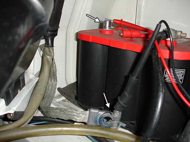
Exist sure to test the voltage at the battery posts and not at the clamps because at that place maybe corrosion that will touch the true reading.
Subsequently this test, my true battery reading shows that it'south downwardly 0.10V (12.7-12.6V) or xc% charged. A battery with a college level of surface charge would testify a much lower final value after the headlights had put the battery under load and then you tin see why testing the initial voltage isn't sufficient.
A seemingly good battery when tested for voltage can exhibit a large voltage drib under load. Go along the probes on the terminals for 10-15s to notice whatsoever continual voltage drops. The voltage should hold fairly steady on a expert battery while the lights are on simply would 0.01V drop every 1-2s on a weak battery. Afterwards 15min if the battery voltage is in the 9.twenty range and all the same dropping you can be sure that it is time to replace the battery because it cannot deliver power for electrical loads anymore.
A battery like this will often bound back to a 12.xx voltage after y'all turn the lights off which demonstrates the importance of taking multiple voltage readings and watching the results while the lights are still on.
Information technology is much easier to find these decremental voltage drops on a digital meter compared to an analog i.
If you tin't effigy out why your battery is running downward when your let you bus sit you may have a current drain issue. The manufactory clock and draws just a few mA and if you lot accept a stereo it might describe some electric current to keep it settings. These accessories are called parasitic loads and they will eventually drain your battery downward to the signal that information technology cannot outset your engine. Connect your ammeter between the battery negative cable and mail service to test for excessive loads. DO NOT start the engine or turn on the headlights or y'all will blow your ammeter. Only an inductive clamp should be used to measure those large amounts of current while the engine is starting/running. Do non connect your ammeter if you are not 100% sure that the electric current describe is less than the current rating of your ammeter if you lot are not using a current clamp and instead measuring it directly.

Anytime the electric current draw is greater than 35mA you lot should suspect an accessory or wiring problem. The best way to endeavor to isolate the issue is to pull fuses i and a time and watch your ammeter to see where the largest drop in current occurs. From there you tin can examine the wiring diagram for that part of the wiring harness to endeavor and pinpoint the problem.
Test ii. Check the electrolyte level
A lead acid battery is so named considering it consists of lead plates and a sulfuric acid solution. The solution is 64% distilled water and 36% sulphuric acrid (H2SO4). If you become this solution on your clothing it will eat through information technology then always be careful effectually an open bombardment. You do not want it getting in your eyes either.
If you have a sealed battery it will often have an indicator on the top that indicates the battery state of charge along with a legend to read information technology. It's usually a colored indicator that shows good, weak and dead. Unfortunately they only exam one of the vi cells so their usefulness is limited.
Many batteries are not sealed and y'all have to bank check on the electrolyte level by popping the sealing caps. Some sealed batteries will let you open up them but simply try this if there are caps on tiptop. Attempting to crack open some other kind of sealed battery is counter productive. I recommend selecting a non-sealed battery in warm climate. They will more than easily allow you to add distilled water that tends to evaporate/boil away in hot weather condition and will extend the life or your battery.
You tin can peer into the filler openings to check the fluid. More frequently that non the electrolyte level is likewise depression from the heat having evaporated the water inside the battery. Considering the bombardment has large plates inside any portion of the plates not covered by electrolyte, will not participate in the electrical reaction. In other words less electric current volition exist produced.
The filler caps are designed to let hydrogen gasses escape and allow the acid mist to condense and driblet dorsum into the battery. Proceed the area around these caps clean and exercise not permit any contaminants to autumn into the battery.
But fill up the battery with distilled water from the grocery shop. Oft y'all can buy a gallon for $1 or so. Make a note of how low each cell is and do not overfill. Cascade in just enough to cover the tops of the plates inside. If you overfill them, they make leak on you if the battery boils over from being overcharged.
Sometimes a battery low on h2o will permanently damage itself. You may exist able to fill, recharge and render the battery to normal only you volition find that it slowly discharges and strands you lot within 2-3 months. When that happens you need to purchase a new bombardment.
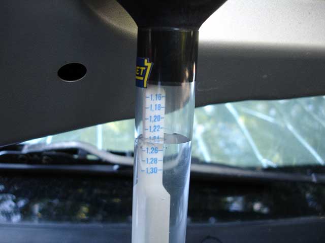
Test 3. Test the electrolyte
The state of the electrolyte is measured using a hydrometer which measures the specific gravity of solution. Y'all insert the hydrometer into the jail cell, squeeze the bulb to suck up the electrolyte and take the reading at the eye level of the fluid. Y'all then return the electrolyte to the prison cell and repeat the process for the other cells. It'southward very important to go along the hydrometer clean otherwise y'all will contaminate the electrolyte and the mineral deposits will interfere with battery cell operation.
Look for a tester that has numbers. The ones with colored balls or a floating strip are hard to read the exact specific gravity.
Specific gravity (SG) is a term from chemistry that indicates the weight of a solution relative to h2o which is given the value of 1.000. Sulfuric acrid has an SG of one.835 and and so a fully charged battery has an SG of 1.270. As the bombardment discharges, the sulphate ions in the solution combine with the lead plates and the solution becomes weaker. Past measuring the solution we can figure out how much charge the bombardment has left.

You may wonder you can't multiply/add one.835 (35% acid) + 1.000 (64% water) to become 1.270? Information technology is because a) the acid solution already had some water content and b) those number are based on a standard temperature which is much lower than the ambient temperature that you lot are taking your measurements at.

Test chart:
| Percentage charge | Specific Gravity at 68F | Voltage |
|---|---|---|
| 100% | 1.265 | 12.67 |
| 75% | one.225 | 12.47 |
| 50% | ane.190 | 12.26 |
| 25% | 1.155 | 12.08 |
| 0 | 1.120 | 11.91 |
If the difference between the higher and lowest value from all six cells is greater than 0.050 you likewise have a bad bombardment. Sometimes a cell fails completely and naturally results in a substantial total voltage drop (either 0V or any reading below 11V) so over again information technology's time to replace that battery.
Some hydrometers are temperature compensating; others are not and calibrated at 80F. If yours is not automobile compensating, and then you must add together 0.004 to your result for every 10F above 80F and subtract 0.004 for every 10F beneath 80F. Luckily this variation is pocket-sized plenty that y'all tin can largely ignore information technology unless you lot are performing your tests at temperature extremes.
Be sure your battery is secured properly: vibration has been known to cause them to fail prematurely.
Battery Charging:
If you've determined your battery is dead and is likewise weak to kickoff the engine, you've got to accuse it. Getting a jump from some other vehicle is an option. Hither's how to do it safely:
- Make sure the dead battery isn't frozen
- Keep cars insulated from each other
- Connect +ve jumper cable from good bombardment to dead bombardment
- Connect the -ve jumper cable from the good bombardment to the engine block or a good ground abroad from the dead battery to avoid sparks.
- Start the booster car (with the good battery)
- Run the booster car for 10 minutes at 2000 rpm to invigorate the dead battery and warm the electrolyte
- Starting time the autobus with the dead battery
- Turn on the headlights and fan on the bus with the dead battery
- Remove -ve jumper cable from skilful battery, then dead battery
- Echo in a higher place with +ve (this will prevent an accidental brusk with the cable)
Your VR won't exist able to tell yous've got a expert or bad battery while connected to the other booster car. One time you disconnect, run your engine at speed for xxx minutes or so and will y'all be able to decide if your battery is charging properly past turning it off and attempting to restart. Do non practise this if you are far from home! When you finally turn off the engine, yous should check the voltages and SG again to confirm if the battery has been partially restored to wellness.
A useful device to own is a battery charger. These are great for keeping shelf batteries charged considering they slowly drain down on their own. These inexpensive models are automated, come in auto and motorcycle sizes. If you utilise the motorcycle units to charge a car bombardment they will taken a long time but still work finer (good to know if y'all accept both types of vehicles because the average automobile charger will over-charge a motorcycle battery).
The manual type chargers are timer based and deliver a college current more speedily. These units are unremarkably very bulky (they have wheels!) and oftentimes expensive. If y'all don't understand the manufacturer's spec on your battery yous may damage it by supplying as well much current.
Remember to ever disconnect the ground cable if y'all are going to charge the battery in the jitney to avoid voltage spikes and limit the voltage that is seen by accessories considering the chargers operate above 14V during some of their charging phases.

Battery Load Testing:
While voltmeters and hydrometers are adept diagnostic tools, once you determine that your bombardment is at least 75% charged, information technology's safe to load exam without further charging. Whatsoever of these tests are suitable:
- Plough on high beams for 5 minutes.
- Disable the ignition and fuel pump/injectors and creepo the engine for 15 secs.
During the test the voltage should non driblet beneath 9.6V. If you wait five minutes afterwards the test the battery should regain information technology's 50% charge voltage level. If either of these tests neglect, you should replace the battery.
If you lot yet aren't sure if your bombardment is bad afterwards testing and attempting to recharge, y'all tin can have it load tested at the local machine parts store. They will often use a carbon pile based load tester that simulates a large current similar a starter would draw. The battery unremarkably needs to have at least a 75% charge before the test and the tester is ordinarily set up to 3x the amp-60 minutes rating of the battery or i/two the CCA rating.
The tester volition have a approximate that shows good/bad and usually a reading of 9.6V or higher during the load examination indicates a skillful battery. The exam lasts 10-15 second max. If the bombardment is not at room temperature, the cut-off for the threshold voltage should increase/decrease 0.1V per 10F change of electrolyte temperature.
Most of these load testers are Non compatible with the newer AGM fashion batteries like Optima. AGM stands for Captivated Glass Matte and the electrolyte is suspended in a gel then the bombardment doesn't leak. You may permanently damage this type of bombardment trying to test information technology at the auto parts store.
Midtronics is a company that makes a new kind of battery tester that is starting to announced at motorcar parts stores. It is compact and easy to use although information technology has varying reports of accurateness. They sell many models but most just provide laissez passer/fail information. This tester measures the conductance of the battery instead of simulating a real load like the carbon pile testers. The conductance (inverse of resistance) changes every bit the surface status of the plates within change. All batteries have some internal resistance inside and the microprocessor inside the tester put the bombardment through a series of tests before rendering a determination. Considering its results are tabular array lookup based, if it asks for the CCA of the battery and you can't find it on the battery characterization you won't exist able to test it and depend on the results.
Some of these testers practice non examination the newer AGM style batteries similar Optima and some practise. Make sure you know the requirements before buying one of these conductance testers. Personally, I don't think they are worth the price.
A discussion about Optima:
Optima is bombardment dissimilar you've fifty-fifty seen before. It's fabricated past Johnson Controls (one the largest battery manufacturers) and is the closest notwithstanding to a leakproof design. If yous are tired of leaks rusting out your battery tray, you need an Optima. They toll more a normal battery but they also concluding longer because they don't lose water long before yous've noticed with a regular battery. They can also deliver a huge amount of starting electric current compared to a normal battery because they have a very low internal resistance of three milliohms.
The Optima 34R is the model that fits our busses (pictured below). 34 is the BCI group number and R means the terminals are reversed (European layout).
| Optima | CCA | CA | Ah | RC | Size (inches) |
|---|---|---|---|---|---|
| 34R | 1000 | 800 | fifty | 110 min | ten x 6 seven/eight" ten seven sixteen/sixteen" |
According to Optima, when fully charged the voltage should be 12.8V and the battery is compatible with any charging arrangement that outputs 13.3-15.0V. When the battery is dead it reads 10.5V.
Terminals:
As the battery terminals corrode, the electrical resistance that builds up is enough to impede both the charging and starting system. A modest 0.ane ohm resistance at the battery terminals can reduce the starter's output by 92% because of the enormous current drawn. The ability to the headlights is also reduced by 32% which reduces the visual intensity by more than 50%. Why does this happen? Ohms law: when the current level is loftier, the voltage drib is proportionally loftier. For instance, 0.ane ohm and 10A = 1V drop.
A majority of charing and starting difficulties tin can be traced to the wiring in the form of corrosion or harm to terminal or sometimes it'due south as simple as loose connection. Either mode, you are bound to experience this on a 25-thirty year old vehicle like a baywindow bus.
Test 1. Check for resistance
The copper ends of the cables corrode as do the lead terminals and the battery posts. Start by measuring the resistance betwixt the final and the battery posts then each end of the cable.


In both cases the voltage you want to meet 0.0V volts with the battery connected or 0.1 ohms or less resistance with the footing cable disconnected. Turn on the headlights when testing the voltage considering a load on the battery will make voltage drops easier to witness. Exercise not turn on the headlights when testing the resistance. Only test resistance with the battery ground cable disconnected.

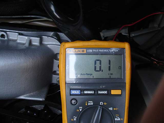
When measuring resistance you want to outset determine what reading yous go by just touching the probes together. Wires and internal components that are role of your meter have resistance that you lot accept to business relationship for in your measurements. If you measure 0.2 ohms and your probes business relationship for 0.one ohms you are actually measuring 0.one ohms.
In add-on to the braided cable connecting the battery negative to the body you must also check the transmission basis strap that connects the starter (via it's casing) to the body. A large plenty voltage drop there will as well crusade starting difficulties (more about this beneath).
Test 2. Clean the terminals
Heavy corrosion can be neutralized and cleaned with a wire brush and a solution of baking soda and h2o. Special terminal cleaners are sold that tin can clean the posts (left) and the cables (right).


When terminals are make clean and dry out, reattach the cables and coat the terminals with petroleum jelly or a special purpose battery terminal spray.
If the corrosion is extensive you lot may have to replace the cable or crimp/solder on a new terminal. Lead based terminals should be avoided because they don't hold their shape and corrode badly. I prefer the high quality components used below. They don't corrode and provide a soldered moisture proof connexion from the cable to the terminals.


Some people insist that you replace the entire cable but that depends on the condition of the cablevision and if they sell cables! A simple last replacement like this can bring your electrical system back to life and prevent the unnecessary buy of a new starter or alternator.
Test 3. Check the starter terminals
You lot also want to clean the large terminal on the starter solenoid. For some reason VW chose non to put a condom kick over these items. Whatever other electrical connexion in the undercarriage that is protected by a boot is usually in smashing shape after 25-30 years. Not so with the solenoid. The large terminal where the battery (black) and alternator (grey) cables meet is last 30.
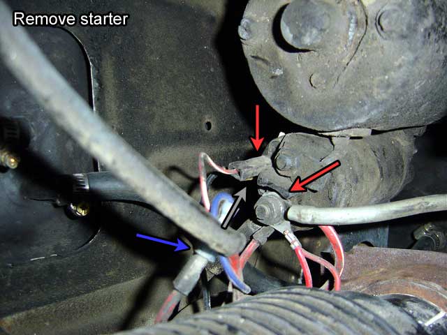
Ignore my remove starter comment in the photo: I reused it from another article.
In addition, you need to make sure yous've got proficient continuity between betwixt all the starter terminals because if you can't start you tin't accuse either. Following the circuit, cleaning and testing:
- Battery +ve to starter (final thirty).
- Starter (final 50) to starter (terminal thirty) via ignition switch
- Starter solenoid to starter body (short basis strap)
- Starter Body to manual (virtually guaranteed good).
- Transmission ground strap to vehicle frame.
- Battery basis strap to bombardment -ve terminal.
Lastly, the bombardment example itself should be make clean because voltage tin can leak from the positive terminal to the bombardment torso to ground through the dust and acid that collects on top. Use a mild baking soda solution and completely dry the battery before installing it.
How does the Alternator work:
Before I explain how to test the voltage regulator and alternator I demand to explicate how both work. If you are familiar with its operation you lot may want to skip the next iii sections.
The alternator charges the battery past reversing the current flow through it and reversing the chemical reaction inside every bit a result. It also supplies electric current to the unabridged electric organization. Fully testing the alternator requires an understanding of how it operates and when it generates voltage and electric current.
The alternator is an electric generator with rectified output. This means that unlike DC generators it produces AC and turns it into DC instead of producing DC directly. This has proven to be a more efficient design than generators because:
- more electric current can exist produced at low rpms
- voltage can exist more than accurately controlled with solid land regulators
- they need less maintenance
- they cost less to industry
If you let your quondam beetle idle, the battery tends to run downward more hands with a generator. Yous may as well notice the charging light on the dash at idle or when driving at night time. This is considering the generator by design has to be driven at a lower max. speed than an alternator which can easily be driven at 2x engine speed. Six volt electrical systems were even worse: the headlight output would increase as yous revved the engine because the generator was and then poor and providing current to keep the battery charged at idle.

An alternator consist of a moving curlicue of wire called the rotor and a stationary coil of wire called the stator. Both coils are wrapped effectually magnets to increase their corresponding electric strengths.
DC current is supplied to the rotor past the voltage regulator and this generates a current in the stator. A slip ring on the rotor is in continuous contact with a pair of brushes as it spins which connect the rotor to the voltage regulator. This is unlike the mechanical switching that occurs in the commutator of a generator which is limiting. The constant contact is possible because the solid state power diodes in the rectifier excursion of the alternator provide the electric current polarity switching function. This also means that no output current passes through the brushes to wear them out prematurely.
To brand the alternator more efficient, three sets of wires make up the stator and because of the way they are wrapped, voltage is produced in three separate phases much like manual in city power lines. The power diodes rectify the iii-phase Ac into a DC-like waveform with very little ripple. This is preferred past batteries as they charge too as electronics you may be operating. The frequency of the Air-conditioning is derived from the speed of the rotor which is governed by the engine speed.
The shape of the rotor is a claw-pole design consisting of an magnetic iron trounce that keeps the wiring inside from flying out (exploding) at loftier rpms. It is a precision machined office with a shaft that runs in two roller bearings. Current flows through the windings of the rotor and the exact amount flowing determines how much current is induced in the stator following the laws of electromagnetism. Precisely metering the output current is the job of the voltage regulator which monitors the battery voltage to determine its load and land of charge.
Alternator Output:
Frequently not well known is that alternators do non produce voltage/current as soon as they start to spin. There is a aught-ampere speed at which the alternator reaches its rated voltage before information technology tin can generate any current. This is typically g rpm (500 engine rpm). I came upward which the 2d effigy because the alternator caster on the bus is half the size of the engine fan pulley and so the alternator spins at twice the engine speed. Next in the serial of important events during alternator spin up is the idling speed: typically at 1500 rpm (750 engine rpm) the alternator must be able to satisfy the needs for long term consumers (basic electrical demands) without running down the battery.
Only above the idle speed is the cut-in speed at which the alternator begins to evangelize current for the start time. The exact speed depends on the battery voltage, voltage from the alternator warning light (pre-excitation power), the rate of change of rotational-speed and the magnetic remanence of the rotor'due south magnets. If you've started your engine and "heard" the alternator irksome downwardly the engine at the outset of fast idle warm-upwards this is the cut-in speed heard in action.
There is likewise a speed rating for the maximum current output, typically 6000 rpm (3000 engine rpm) and there is a maximum rpm at which the alternator tin can spin which is dictated by the roller bearings and carbon brushes within also every bit the fan because it accept power to pull air through. On average this limit is xx,000 rpm (x,000 engine rpm): much higher than any stock VW engine can reach and any that practice are elevate racers who accept no need for an alternator (substitute a dry cell battery or magneto powered ignition system).
Finally, the alternator can't run all day long at 100% duty cycle (fourscore% is more than reasonable) and then you should factor your current load requirements with that in mind.
How the Voltage Regulator Works:
The voltage regulator controls the field electric current in the rotor of the alternator. It measures the voltage of the bombardment (decreasing) and by changing the electric current (increasing) in the rotor, more voltage/current (increasing) is produced in the stator of the alternator which is used to charge the battery. This inverse relationship between the voltage regulator and the alternator is all that'southward required to continue the battery charged and the electrical system powered most of the fourth dimension.
The earliest voltage regulators installed on baywindows were mechanical relay based devices merely they have been replaced by longer lasting more than accurate solid land versions. Both styles are configured to produce 14V from the alternator and no more than, hence their namesake. The mechanical versions are the easiest to sympathize and then I'll skip the details of the microcontroller and NPN power transistor wiring in the solid land version.
If the alternator were run at idle speed on a demote you could measure out the output current/voltage past changing the input current. The slip band path through the rotor has a fixed resistance so according to ohms police (I = V/R) y'all tin can increase the current to the rotor simply by varying the voltage. This is the basis for how the voltage regulator controls the alternator's output.

In the diagram the left paradigm shows the bones wiring layout and the 3 diagrams on the right testify how electric current flows in the 3 stages of operation. Yellow arrows indicate small current flow while orangish arrows bespeak a larger current flow. The voltage regulator takes a 3 wire input which is uses to sense the alternator voltage and control it:
|
|
The blue wire leads to the warning lamp in the instrument panel and the red wire at B+ leads to the battery (via the starter solenoid). Using the legend in the wiring diagram section of Bentley'southward electrical affiliate, you can learn to read the VR internal wiring schematic: inside is a relay controlling two contacts and a few resistors. The black block to the left of C represents the rotor inside the alternator.
The VR operates in three stages. The first stage (key on) initiates when the ignition primal is turned to the on position but before the engine is started (alternator off). Ability from the ignition switch flows through the alarm lamp and through the rotor field winding in order to excite the alternator.
In stage ii (alternator on) the engine has started, the alternator spins upwards at 2x engine speed and near the alternator's nix-ampere speed (effectually 500 engine rpm), it begins to produce voltage at B+ through one set of diodes which is fed to the battery and also to D+ which is picked upwards at the voltage regulator. The voltage at D+ follows B+ but varies slightly because D+ receives its signal from the stator through a carve up gear up of diodes.
With similar voltage at both ends of the warning lamp now, it goes out. Information technology's as well interesting to note that the nada-ampere speed is largely determined by the power rating of the warning lamp. In our case, information technology's a normal 1.2W musical instrument low-cal bulb.
The voltage at D+ is fed to DF past the VR and the increasing magnetic field in the rotor induces an alternating current in the stator which is rectified into DC and fed to the battery via B+. The output voltage varies according to the input voltage (fed back into the rotor by the VR) and the engine rpm.
In the 3rd stage (alternator idle) the output voltage has reached the 14V set bespeak at which time the relay (whorl) inside the regulator energizes and breaks the contact inside which connects D+ and DF and shunts DF to footing via D-. While the majority of current flows to ground, a small-scale current is fed through the rotor so the alternator isn't completely turned off. The diodes inside the alternator protect it from the bombardment at all times during these switching operations.

Equally the voltage drops at B+, the relay contacts re-open and the VR cycles to phase 2 and the procedure begins all once more. The voltage is controlled using a variable frequency duty bicycle approach. This system is pretty dotterel and slow to respond. It'south hoped that a) any sudden changes are absorbed by the battery b) a 10V "dead" battery won't exist present to force the alternator to run 100% duty cycle trying to charge it. These are two reasons that solid state regulators are so much ameliorate: the better ones are microcontroller based and understand a lot more than about the land of the electrical organization than a simple relay. You lot just have to brand sure y'all invest in i from Bosch (0 192 062 007) pictured right and not a piece of junk from Autozone. The latter contains an underpowered switching transistor and merely about $1 worth of electronic parts inside.
Solid country VRs can besides exert much finer command over the rotor'south field voltage. At low rpms the field voltage tin can be set high to aid the alternator go along the bombardment charged considering it'due south less efficient at depression rpms. Every alternator has a spec that describes a bend of current output vs. engine speed which tend to rising sharply effectually the idle speed and and then level off.
At higher rpms, the alternator output is sufficient that merely a low voltage is required. When the battery voltage is depression (high electric current drain) the rotor voltage is increased to increase the output. All this happens instantaneously as the solid state VR monitors the battery and alternator as the electric load and rpms change. How does it accomplish this control? By sensing the phase of the output voltage it can determine the rotor speed. As a side notation, fifty-fifty though the alternator output is rectified from AC to DC, some of the AC leaks through the diodes and appears as a DC ripple.
When the regulator fails, the battery is either a) in danger of existence overcharged or b) fails to charge. When the voltage level is too loftier most batteries will give off gas every bit the sulphuric acid and water in the electrolyte decomposes into hydrogen and oxygen. Think the Hindenburg? You lot don't non want whatever sparks to occur when this is happening which is why the jump starting tips recommend that you connect the negative jumper cable to a proficient engine basis away from the battery negative post.
Testing the Voltage Regulator:
Now we know how the system works, nosotros can easily diagnose it. E'er check the regulator earlier the alternator because they fail more than ofttimes.
Test ane. Indicator Lamp
If the lamp is non coming on when yous plow the cardinal to on you demand to verify that the bulb is good. If the bombardment is connected then the bulb should be getting battery voltage. What is oftentimes misunderstood is the back of the musical instrument cluster is not made from a single piece of metal. Most of it is grounded to the body by the circle of spaded connectors on the back merely the surface area where the indicator/warning lights reside is insulated by plastic, sometimes in 2 separate sections. You'll meet a tab on that insulated section to provide 12V simply for those lights instead of the usual footing.
Since it's merely a bulb information technology tin burn out similar whatsoever other instrument lamp. To change the bulb you don't need to remove the instrument cluster but I would propose you lot to disconnect the battery before you accidentally brusque out the musical instrument panel and smoke the instrument wiring harness or get-go a fire.
Examination 2. Verify voltage at harness plug
To test the regulator you need a voltmeter and a set of probes that can reach into the underside of the connector to bear on the terminals. Undo the right-side mounting screw and the let the VR rotate 90 CW so you can more easily access the underside of the connector.

| Land | D+ (reddish/blue) | DF (green) | D- (brown) | Lamp |
|---|---|---|---|---|
| Ignition off, engine off | 0V | 0V | 0V | off |
| Ignition on, engine off | ane.28V | 0.64V | 0V | on |
| Ignition on, engine idle | 14V | 5V | 0V | on |
| Engine on (fast idle) | 14V | 5V | 0V | off |
Note: All voltages are DC. If you try to measure the AC voltage at DF with the engine running you should see only a few mV. The DF voltage with the engine on depends on the bodily battery voltage. You will encounter ~5V on a fully charged battery and up to 12V as the SOC of the battery decreases. When the engine is off it will likewise depend on the bombardment voltage (SOC + electric load) and the reading volition exist less than 1V.
It takes very little time for the engine to spin the alternator fast enough to generate full output voltage. If y'all take to rev the engine to get the warning calorie-free to become out y'all volition probably confirm an alternator problem by measuring a battery level voltage at D+ with the primal on and the engine off. A reading of 1-2V reading at both D+ and DF after the engine starts indicates a diode problem in the alternator.
Mensurate the battery voltage with the engine running. It should be thirteen.8-xiv.ii even with the lights on. The exact voltage depends on your alternator and wiring resistances but information technology's not uncommon to see a 0.iv-0.8V drop with the lights on. You'll find that the mechanical voltage regulators have trouble keeping the voltage correct at 14V when the system is under load.
If the VR seems to be charging the battery correctly and so a total-field exam of the alternator should exist performed.
Test 3. Test the regulator
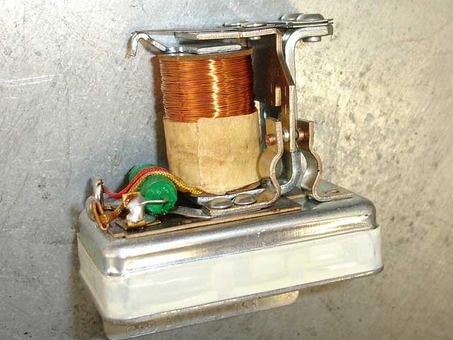

If your voltage regulator is mechanical you should experience information technology clicking. If you can't feel it above the engine vibration, y'all'll need to open it up. Past looking at the photo you might wonder, did Bosch really but seal it upwards with tape. Yeah! To remove the cap, but cutting the record in the middle all the way around with a utility knife and advisedly wiggle the top off.
Within is a field coil (solenoid), a choke and a pair of contacts that resemble a set of Bosch ignition points. The scroll is connected across D+ and D-. When the ignition is on, bombardment voltage at D+ comes from the ignition switch and flows through the points to the rotor. This is the initial excitation that the alternator requires. When the alternator starts producing the 14V set point voltage, the roll energizes, breaks the contacts and the field current goes near to zero. The choke exists to limit the arcing through the points.
If the mechanical regulator hasn't burned out you should encounter these readings when measuring resistance between terminals:
- D+ and DF - 0.3 ohms
- D- an DF - open
- D- and D+ - 80 ohms
If you have the later way VR with a existent power transistor mounted on the bottom (solid state), then your readings will be very different and then don't worry.
On the bottom is a thermal resistor that drops in resistance as the intake temperature decreases. The purpose is the alter the charging ready bespeak because batteries can exist charged to college voltages in the cold. Similarly when they get too hot, the prepare betoken is lowered in order to keep them from humid over.

It's non possible to test the thermistor without switching the contacts inside because the current from your ohm meter takes the path of least resistance which is between D+ and DF. You have to open up the regulator and toggle the switch by mitt. Take the thermistor reading betwixt D+ and DF. It should read about 2.3 ohms at 68F and decrease with temperature (a quick blast of cold spray will confirm).
If the regulator checks out, so yous need to perform a full-field exam of the alternator to dominion the VR out completely. This involves, disconnecting the plug from the VR and connecting the bombardment positive via patch cable (preferably at the B+ concluding on the alternator) to the DF (green wire) terminal of the plug. Now run the engine for a few seconds; just long plenty to verify voltage at the battery. This should only be done for an instant considering the voltage coming out of the alternator will be unregulated but it will determine if the VR needs to be replaced or if the alternator is at fault. Because nosotros've bypassed the VR, sensitive electronics maybe at risk! If your engine is fuel injected I recommend that you lot accept the alternator to an alternator repair shop for a full field bench test instead (tests are usually free).
Does it get hot? Sometimes it tin. The VR takes 12V from the battery as input. If information technology needs to pass 2A of electric current through the four.5 ohm rotor to enhance the output voltage to 12V that means it has to send 9V through. This means it has to absorb 3V at 2A of current which equates to 6W of ability that information technology has to misemploy as heat.
Examination 4. Exam the wiring harness
This isn't an like shooting fish in a barrel stride with the alternator installed but it is possible. You need to disconnect the harness plug from the alternator to test the resistance of each wire. Resistance should be 0.i ohms or less. Corrosion is usually heavier on the alternator side but you should likewise examine the voltage regulator plug including the wiring that leads to the indicator light on the dash. Use a pick and bend the tabs inside from the front end to remove the uninsulated terminals from the rear. Desperately corroded terminals tin can be replaced easily considering this harness tends to take a lot of slack in information technology.
If the wire is bad, you lot'll accept to replace the wiring and shrink wrap it. I recommend using the aforementioned colors and be sure not to get the colors mixed up when you reattach the terminals to the plugs or you'll smoke the alternator.
Testing the Alternator:
Test 1. Concrete indicators
Is the chugalug tight? If it's likewise tight it will identify a side load on the bearings and prematurely wear them out. If it's too loose, it may slip on the pulley and non spin the alternator fast plenty. Excessive slipping noises are always obvious but non ever nowadays. The chugalug stretches and requires re-aligning, especially later on you install a new 1. I've fifty-fifty seen belt stretch from the engine well-nigh overheating in extremely hot/dry weather.
Since the rotor is magnetic yous tin test that it is getting current without disassembling it (the VR has to be working with the cardinal on for this examination):
- Engine off - no magnetism between caster nut and screwdriver.
- Engine on - attraction ways magnetic field is nowadays so brushes and rotor are making good contact.
Be certain to test that the screwdriver has no residue magnetic pull before you test information technology against the alternator. If there is little or no pull on the screwdriver, unplug the VR and curt the scarlet and green wires together. Now plough on the central and this volition provide the rotor with a direct 12V field which should increase the magnetic pull.
If at that place is still no pull, exam the voltage of the red wire. If there is no voltage the harness maybe broken or not making proper contact. If in that location is still no magnetism and so the alternator maybe bad (diode, short, etc).

Exam 2. Full field test
This was described above in the VR section. The alternator should produce xc% of its rated output during the test to exist considered good. In the photo you lot can see the technician at the rebuild shop just uses a large electric motor to spin up the alternator. They all seem to have this kind of home fabricated setup and usually accept some hard to read oscilloscope.
Keep in mind that alternators are designed to operate at 80% or and then duty cycle. When you lot drive the alternator with total input voltage at DF you risk damage to it unless the test is brief.
Test 3. Electrical faults
 | A Bosch alternator has nine diodes: iii negative and three positive power diodes form the full-wave bridge rectifier that catechumen AC to DC. And so at that place are three smaller isolation/excitation diodes. The concluding iii are the ones that control D+ on the voltage regulator only nearly machine part stores have no inclination of testing them: they apply a voltage to DF, spin it up, the alternator puts out 90-100% rated amps at B+ and they say it's practiced but that test doesn't prove the alternator is working correctly! If the output waveform at D+ isn't checked yous can't be sure the alternator is working!!! Abnormal output at D+ is usually caused by bad diodes. For instance, a high cut-in rpm is a common side-outcome of diode failure. |
The reason for testing the smaller isolation diodes properly is that when they fail the VR will exist confused and non know how to command an alternator that can otherwise output full voltage/current. They provide the voltage signal used to determine the battery voltage. If the test is skipped, you may simply get back home with your alternator, reinstall it, replace the regulator on the advice of the auto parts store and notwithstanding have charging problems. Y'all need an oscilloscope to detect this without disassembling the alternator.
Charge per unit their test procedure...a complete test of the alternator would consist of:
- rotor continuity
- stator continuity
- full field test for maximum power output (980W for 70A)
- maximum output power under total load (70A)
- voltage regulator gear up point (14V)
- voltage regulator set up betoken hot (temp compensation)
- cutting-in speed (indicator lamp out)
- output waveform
- ripple voltage @ maximum output
- rectifier diodes voltage driblet and forward electric current tests
- rectifier diodes leakage electric current tested at 12 volts
Of course, since the test is free, they merely do the minimum: full field-examination.
Disconnecting the battery while the alternator is running can fry the diodes inside so never practice that even when the engine if turned off. You should not practise this in lodge to test the alternator by seeing if the car notwithstanding runs or past checking the voltage at the battery. The battery also acts similar a huge capacitor that smoothes out the power delivery from the alternator. Sensitive electronics may fry if yous run the alternator without the battery.
Alternator Habiliment:
If the alternator checks out electrically, you lot however demand to audit the parts so you lot don't get stuck on the road. Alternators have a limited life earlier they crave rebuilding. You lot can expect to get 200k miles out of a factory unit. By that time, you will have ane or many of the following problems:
- Worn bearings
- Worn brushes
- Worn sideslip-rings
There should be no side to side play in the rotor/pulley. That indicates your bearings are shot. In there is excessive endplay information technology means that the rotor is not press fit to the bearing anymore or the drive end bearing retaining cap has come loose and the bearing is no longer press fit to the drive end plate (housing).
Bearing replacement requires complete disassembly. Often the bearings are and so former that the grease inside has dried up, go contaminated or no longer contacts the bearings. Bearing grease tin can dry out long before the expected life of the bearing is reached, and so you lot may accept worn bearings afterward 100k miles if your alternator sat unused for many years. If the bearings spin hands and make a metallic rolling sounds they are wearing. If you hear any grinding noises they are finished. Just a silent bearing that spins down very quickly is in excellent condition.
Worn brushes are a simply thing of replacement. The brushes are carbon based and a bound presses them against the slip-rings. When the springs are fully extended (near 4-6mm of clothing) they no longer make practiced contact with the sideslip-rings. Brushes should be inspected every 75k miles on a Bosch alternator.
Quite often the symptom of worn out brushes is a a flickering warning light on the dash.
Worn sideslip-rings are a more than involved repair. The slip-rings are fabricated from copper and the brushes cleave a groove into them. You lot tin plow the sideslip rings if they are not as well worn merely the mileage of the alternator volition depend on how much copper is left. At some point the slip rings accept to be removed, replaced and re-soldered to the rotor.
Racket mainly comes from worn out bearings. With the engine running your cannot hear the noise from worn brushes although you tin hear it when you spin the rotor by paw besides as see it on an oscilloscope.
References:
- 70A Alternator
- Alternator capacity (Type2.com)
- How your VW charges the battery
- BCI
- Battery Basics (batterytender.com)
- Battery corrosion (Hyperphysics)
- Batteries are not 12V
- Optima technical specs
- Optima charging specs
- Midtronics
History:
07/17/05 - Created
09/24/05 - Updated with photos
09/08/11 - Fixed broken photos, added translate button, updated footer
07/15/xix - Google update: new adsense code, removed defunt interpret push
Source: https://ratwell.com/technical/ChargingSystem.html
0 Response to "Battery Reading 12.36 Volts but Battery Still Acts Like a Dead Battery"
Postar um comentário